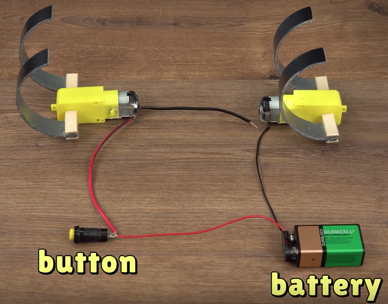
Simplified control circuit of the minirobot Circuit Diagram Maze Solving Robot Arduino Code. The maze-solving robot uses IR sensors to detect obstacles and employs a logical decision-making algorithm to navigate through a maze. The robot's movement is controlled via DC motors interfaced with the Arduino Motor Shield V1. Below is a detailed breakdown of the code. In this tutorial, we are going to design an Arduino Uno based Robotic Arm from some cardboards and servo motors.Entire process of construction has been explained in detail below. Here in this project Arduino Uno is programmed to control servo motors which are serving as joints of Robotic arm.This setup also looks as a Robotic Crane or we can convert it into a Crane by doing some easy tweaks.

The receiver and motor driver circuit (Fig. 3) is built around Arduino UNO board (BOARD1), decoder IC HT12D (IC2), 433MHz RF receiver module (RX1), motor driver IC L293D (IC3), regulator IC 7805 (IC4) and a few discrete components. Fig. 1: Block diagram of Arduino based RF controlled robot Fig. 2: Circuit of transmitter section Arduino UNO board For example, if the object moves to the left, the robotic arm will respond by moving to the left, and similarly for movements to the right, up, and down. 4 DOF Acrylic Robotic DIY Arm Kit. 1. 16-Channel 12-bit PWM/Servo Driver I2C interface PCA9685. 4. Tower Pro SG90 Servo Motor. Tools and machines. Soldering Iron Kit. Apps and platforms. 1. It is better to make DIY Arduino Robotic Arm since Industrial robotic arms are very expensive because of complex sensors and high accurate motors, in this project we will make budget friendly robot arm.. Features of Arduino Robot Arm. Uses micro servo for movements. Controlled by potentiometer. Can be use to pick and place objects since Rotation up to 180 degree is possible
DIY Arduino Robotic Arm Project with Circuit Diagram & Code
You can also control the robot's speed. That's why I named this robot an 'All-in-One Robot'. Let's dive into its story—a mix of tech, fun, and endless ideas. Features: Bluetooth Control: Seamlessly control the robot using a custom-made mobile app created with MIT App Inventor. Enjoy the convenience of wireless control from your smartphone.
Arduino Robot Arm Circuit Diagram. The next stage is connecting the electronics. The circuit diagram of this project is actually quite simple. We just need an Arduino board and a HC-05 Bluetooth module for communication with the smartphone. The control pins of the six servo motors are connected to six digital pins of the Arduino board. Explore 75+ DIY robotics projects with detailed circuit diagrams, source code, and complete instructions.Whether you're a beginner or an advanced maker, you'll find exciting projects using Arduino, Raspberry Pi, ESP32, and other microcontrollers.From line-following robots to AI-powered bots, our tutorials make robotics easy to learn and build.