control algorithm for LED shift register Circuit Diagram Code to Control LEDs using the 74HC595 Shift Register. Firstly, it allows you to control multiple outputs using only a few Arduino pins, which is especially useful when you have limited pins available. Secondly, it reduces the amount of wiring required, making your project more organized and easier to manage. Using a Shift Register to Control a Bunch of LEDs. Shift registers are very useful tools; using a few pins connected to a shift register, we can increase the number of output data pins that are available to us. In this experiment, we'll be using a shift register to control eight LEDs, but we'll only be using three pins from the ATmega. In order to save on pins I am using a shift register to control the columns. This way I can control an almost unlimited number of columns with just four microcontroller pins. It is possible to use only three if the Enable Output pin is tied directly to voltage. I have selected the HEF4794 LED driver with shift register.

🚀 In this tutorial, we'll learn how to use the 74HC595 shift register with an Arduino Nano to control 10 LEDs with different lighting modes. This method hel

5.1 Using the 74HC595 Shift Register — SunFounder Newton Lab Kit for ... Circuit Diagram
Connecting the shift register; Connecting the LEDs; Connecting your Omega; It's going to be similar to the second experiment, but this time we're going to use 8 LEDs and a shift register. Refer to the circuit building instructions in Experiment 2, except you will be connecting 8 LEDs to the shift register instead of the Omega's GPIOs.

Fig: 74HC595 Shift Register. The 74HC595 is an 8-bit serial-in, parallel-out shift register.It is a popular IC used for expanding the number of output pins on a microcontroller. By using a shift register like the 74HC595, you can control multiple outputs, such as LEDs, with just a few pins from your microcontroller.This makes it ideal for projects where the microcontroller's pins are limited
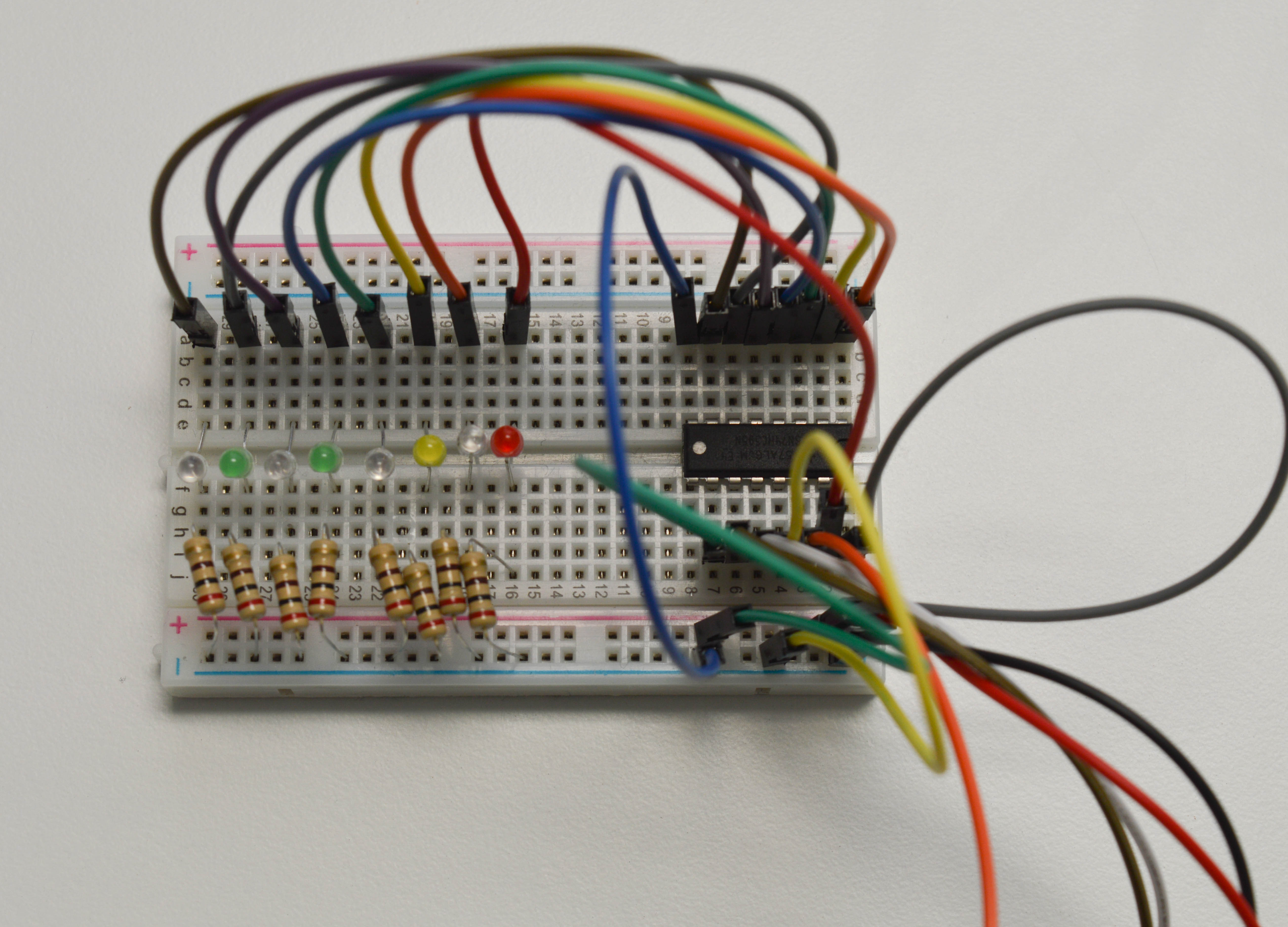
Using a Shift Register to Control a Bunch of LEDs Circuit Diagram
This demonstrates how the 74HC595 shift register can be used to control multiple outputs with only three control pins from the microcontroller. Conclusion This experiment shows how the 74HC595 shift register can be used to expand the output capabilities of a microcontroller, allowing it to control 8 LEDs with only 3 digital pins. 5.1 Using the 74HC595 Shift Register . In this lesson, we'll learn how to use the 74HC595 shift register to control multiple LEDs with just a few GPIO pins on the Raspberry Pi Pico 2. The 74HC595 is an integrated circuit (IC) that allows you to expand the number of digital outputs using a serial input.
