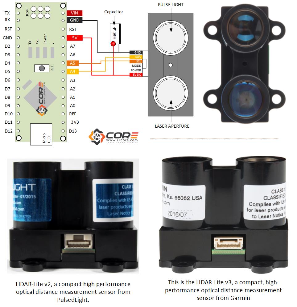
AccuracyPower Controllable LiDAR Sensor Circuit Diagram The board has UART and I2C Interface. the board has a microcontroller like STM32 Series controller or something equivalent to it. By connecting the sensor to any external microcontroller, you can retrieve the LiDAR data. It has 4 pins as Power Pins and the UART Pins.The RED color wire is the VCC & Black is the Ground.While the White color wire is RX and Green is the TX. Circuit diagram. The code. To begin, we included the I2C general library (wire.h) in Arduino sketch, followed by the LiDARLite library from SparkFun. So, an instance of the LiDARLite library is created. For example, look at the below images of trees in front of a LiDAR sensor. From a set reference point, the distance and angle of the light The Garmin LIDAR-Lite v4 sensor requires 5V to operate. In order to provide 5V to the sensor from the 3.3V line of the Qwiic connector, a DC-to-DC voltage converter is utilized. This can also be referred to as the buck/boost converter/circuit.
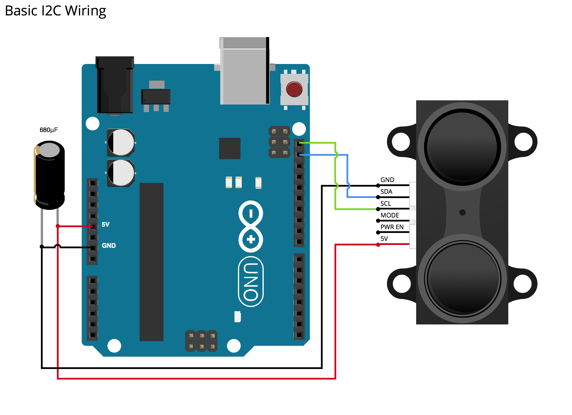
Then, connect the red wire (pin 1 of the TFmini Plus to the 5V output of the Arduino. For UART, connect the white wire (TX, pin 2) of the TFmini Plus to pin 3 of the Arduino. Finally, connect the green wire (RX, pin 3) of the TFmini Plus to pin 3 of the Arduino. See the complete wiring diagram below: Mode-control connection Yellow wire 5 Vdc power (+) connection Red wire The sensor operates at 4.75 through 5.5 Vdc, with a max. of 6 Vdc. PWM Arduino Wiring Item Description Notes 5 Vdc power (+) connection Red wire The sensor operates at 4.75 through 5.5 Vdc, with a max. of 6 Vdc. Power ground (-) connection Black Wire
PDF Adafruit VL6180X Time of Flight Micro Circuit Diagram
The TFMini is a ToF (Time of Flight) LiDAR sensor capable of measuring the distance to an object as close as 30 cm and as far as 12 meters! The TFMini allows you to integrate LiDAR into applications traditionally reserved for smaller sensors such as the SHARP GP-series infrared rangefinders. Wire Color; 1: UART_TX (3.3V TTL) Green: 2: UART LIDAR Distance Sensor Breakout Created by lady ada read the text on the breakout to match the pins to the wiring diagrams. ©Adafruit Industries Page 10 of 29. Connect Vin to the power supply, 3-5V is fine. Use the same voltage that the microcontroller logic is based off of. For
This is another illustration that demonstrate how to wire the LIDAR Sensor on your Microcontroller. LIDAR (Light Detection and Ranging) is a remote sensing device which is capable capture geographical information. LIDAR data is often collected by the survey of aircraft or ground vehicle. NOAA scientist use LIDAR devices to examine both natural and man-made
